LED with button battery
Normally, the computers that we use day to day (such as laptops, desktops, tablets or smartphones) have only high-level peripherals (sockets for USB-, HDMI-cables or the like). This makes it a little problematic to connect devices to the computer so that we can control them with our programs.
The Raspberry Pi however has sockets that we can use to easily control simple devices. The following projects introduce programming with Scratch to control LEDs and read push-button states and ultrasonic readings.
LEDs
LEDs are fun and easy to control. One thing to keep in mind is how they are oriented. The long end needs the positive voltage while the short one is ground/negative. A good way to show this (and introduce LEDs is to connect them to button batteries as shown below:
MYND!!
For a simple switch, one can put some tape on the LED side of one of the battery faces to create some space between the LED pin and the battery face. By squeezing the pin onto the battery face we complete the circuit and light the LED.
Connecting the LED to the Raspberry Pi
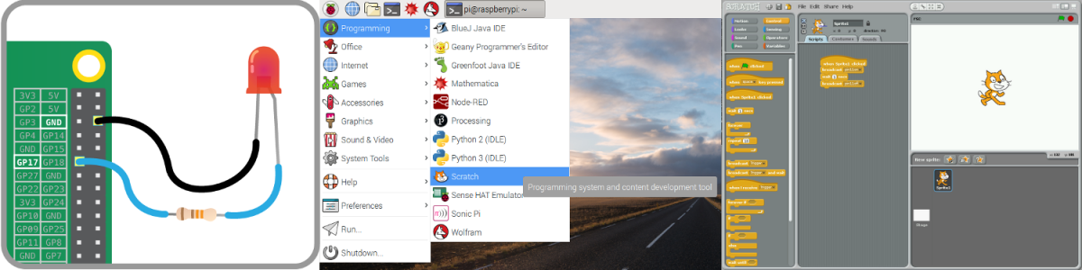
Note that the standard Scratch interface doesn't work with the GPIO pins. For this we will need a patched version called ScratchGPIO which is installed on the Raspbians.
For the first part of this project you'll need:
- An LED light
- A 330 Ω resistor
- Three female-to-female connectors
And for the second part:
- A push-button
- A breadboard
- Several female-to-male connectors
- A bundle of male-to-male connectors
Go to this worksheet on the Raspberry Pi Foundation website and follow the instructions. Once you have finished the projects and found out how to control an LED with a push-button, you can jump ahead to the next project or do come up with a project of your own.
You can for example add more lights and create a little show, an interface for a clock or a counter, a traffic light or come up with a computer game to interact with using one or more buttons.
With the basic concepts in place (instruction flow, loops/repetitions, conditionals and variables) programming offers an exceptional opportunity for students to follow their own interests. Rather than force them to learn how to connect a bunch of devices (which they can easily learn from a whole host of on-line resources) we recommend allowing the students to follow their own interests.
Ultrasonic sensor with Scratch
There is an enormous range of sensors available for the Raspberry Pi (these generally work interchangably with the Arduino). For this session we have ultrasonic sensors. Many sensors are much simpler to connect, some (such as most light-sensors) are just connected between ground an a pin. The ultrasonic sensor, however, allows for quite sophisticated sensing of the environment without having to do any camera image processing.
For the first part of this project you'll need:
- An ultrasonic sensor
- A 1 kΩ resistor
- Two 2.2 kΩ resistor
- Two male-to-female connectors
- Two male-to-male connectors
The developer of ScratchGPIO has made reading from the ultrasonic sensor extremely simple: It's just a matter of broadcasting a message to the trigger/echo pin and reading from it a second later. See the instructions on the ScratchGPIO Ultrasonic Sensor Boards.
You can now read from the sensor and use the output to control other devices such as motors or LEDs such as those in the previous project. To find all kinds of uses for the ultrasonic sensor, you're advised to ask uncle Google. One example is this Press Up (Push Up) Counting Machine using Scratch.
Ultrasonic sensor and LED with Scratch
Once you have your sensor set up, have your program react somehow to the reading. For example, control the number of pins being lit.